


Elevator installation requirements are the site conditions a building has to meet before a lift can be assembled: a plumb hoistway, a dry pit with drainage and access, landing openings cut to the door hole size, overhead support, and a three-phase supply. Any one of them missing stops the crew on arrival, not at handover.
What this page covers
- What elevator installation requirements actually cover
- Seven conditions that stop a crew on day one
- Hoistway tolerance: plumb, square and clear
- The pit: what has to be down there
- Landing openings and sill support
- Overhead support and machine room loads
- Site access, storage and construction power
- Who builds what: the civil works boundary
- The site survey you send before shipping
- Choosing and briefing the installation team
- The fifteen-item readiness checklist
- Frequently asked questions
What Elevator Installation Requirements Actually Cover
An elevator order involves three separate sets of duties, and only one of them ships in the crate. The building has to be ready, the equipment has to be correct, and somebody has to assemble it. Elevator installation requirements are the first of those three, and they are the only one a supplier cannot fix after the fact, which is why they belong on the buyer’s critical path rather than the supplier’s.
Sizes are a different problem. Pit depth, overhead height and shaft width are set out in the elevator shaft dimensions guide, together with the pre-pour checks that fix those numbers before concrete. Read that first if the shaft has not been poured. Come back here once the numbers are fixed, because a shaft of exactly the right size can still be a shaft nobody can install in. Those numbers are the part of elevator installation requirements a drawing can carry; the rest needs a site visit.
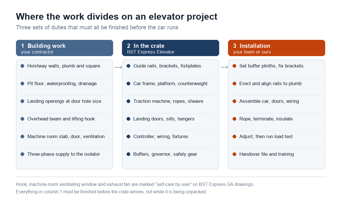
Dimensions are the easy part, and they are the only part most quotations check. The rest of the elevator installation requirements are the conditions a crew walks into on the first morning: what they measure, what they will not work around, and which of the three parties was supposed to have fixed it.
Seven Conditions That Stop a Crew on Day One
Each condition below has the same property: the installation team cannot solve it with the material on site. It needs a contractor, a crane or a concrete cutter, and none of those are booked for the week the crew flies in. These seven are where elevator installation requirements are most often incomplete at the moment of delivery.
| Condition | What the crew checks first | What it costs if it fails |
|---|---|---|
| Hoistway out of plumb | A plumb wire at each landing, offset measured to the wall face | Rails cannot be aligned, brackets are packed past their limit, and the car runs noisy. |
| Pit wet or undrained | Standing water, the sump, the waterproofing, and where the drain actually runs | Buffers and safety gear sit in water, the crew will not start, and corrosion begins early. |
| Landing openings the wrong size | Every opening, width and height, against the hole figures on the GA drawing | Sills will not fit and the entrance finish cannot close, so concrete is cut on site. |
| No overhead support | The beam, the cast-in anchors, and whether the lifting hook exists | The machine cannot be lifted to the top of the shaft, and a crane is hired for a single lift. |
| Machine room unfinished | Slab level, door size, ventilation and permanent light | The controller cannot be commissioned, and a room that runs hot shortens drive life. |
| No three-phase supply | Cable size, breaker, earth bar and phase labels at the isolator | The lift cannot be run at all, and the crew waits on the utility instead of working. |
| No access and no dry storage | Truck turning space, a hoist or crane, and a lockable dry room | The crate sits on the truck, and parts are lost, stolen or rained on before they are opened. |
Seven items, any one of which turns a two-week job into a two-month one. The pattern is worth noticing: almost all of them are invisible on a dimension drawing, which is why they survive a drawing review and then surface as an argument on site. A written schedule of elevator installation requirements schedule prevents that, because it puts a name against each line.
Hoistway Tolerance: Plumb, Square and Clear
A hoistway is specified by its clear width and depth, but it is built by a formwork gang thinking about the building grid rather than about guide rails. The two interests rarely agree to the millimetre. What matters for elevator installation requirements is not the average size of the shaft but how far it wanders between the bottom and the top. Both are measurable, and both belong on the elevator installation requirements sheet before the rails are ordered.
The practical check is a plumb wire dropped from the top landing to the pit, with the offset to the wall face measured at every floor and written down. Where a shaft tapers, rails can usually still be aligned, but brackets need packing and the clearance between car and wall changes over the travel. Where a shaft is twisted, the rails fight each other and the ride never comes clean.
Nothing should protrude into the shaft either: formwork ties, a stray conduit, a beam end, a brick course that was never cut back. And the front wall plane at every landing should be checked, because landing doors are set from that plane. If it steps in and out between floors, the frames step with it, and that shows in the finished lobby long after the crew has gone. Neither protrusions nor a stepped front wall show up there, and both are elevator installation requirements in the strict sense, and neither appears on a drawing.
Fire separation is the elevator installation requirements item most often forgotten. The hoistway wall is a fire compartment boundary in most jurisdictions, and the openings the crew makes for the machine beam, the cable tray and the pit drain have to be sealed afterwards. Agree in advance who seals them, because by then the crate is empty and the crew is on the way out.
The openings at each landing are the harder case, because a fire rated landing door only holds its rating when the frame and its seal are installed as the tested assembly was.
The Pit: What Has to Be Down There
The pit is measured for depth and then ignored. On the elevator installation requirements list it should appear four more times, because a pit that people will work in needs four things that a depth measurement does not cover.
Water is first. The floor slab has to be waterproofed and has to drain, either to a sump with a pump or to a drainage point that actually runs somewhere. A pit that collects water destroys buffers, rots the safety gear and stops the crew from starting, which makes drainage the cheapest elevator installation requirements item on the list. Second is access: a fixed ladder or an access door, not a ladder borrowed from the main contractor.
Third is permanent light and a socket at pit level, so that nobody runs an extension lead down a shaft. Fourth is a level base for the buffer plinths, cast to the position on the GA drawing rather than guessed after the rails are up. The buffers are what the car lands on in a fault, and their height sets the car’s lowest stopping position. Both are cheap in a new build and expensive in a retrofit, which is why they belong in the elevator installation requirements from the first drawing.
A pit stop switch at the ladder belongs in the elevator installation requirements too, before anyone works below the car. If it is missing, the crew will wire a temporary one in, and temporary fittings are exactly what get left behind at handover.
Landing Openings and Sill Support
The door hole is where the building and the equipment meet with the least tolerance for error. On BST Express Elevator GA drawings the hole is dimensioned from the finished opening: door hole width equals net door width plus 200 mm, and door hole height equals net door height plus 100 mm. Those two figures carry most of the elevator installation requirements for a landing, and they are the first thing the crew measures on arrival.
Under every opening sits the sill. A sill carries the landing door leaf and its bottom guide, and it takes the weight of a person standing on the threshold, so it cannot float on a mortar bed. It needs a support: a cast-in angle, a steel flat bolted to the wall, or a recess in the floor slab that the sill drops into. Which of the three is used is a drawing decision, but it has to be made before the floor is finished.
Entrance finish is the third item. Marble, tile or stone returns need a margin around the door frame and are normally fitted after the lift is running. The opening therefore gets built to the hole size and left unclad, rather than built to the finished size and clad early. Projects that do it the other way round end up pulling frames out. Hole, sill support and finish are three elevator installation requirements that fall due weeks apart, in that order.
Overhead Support and Machine Room Loads
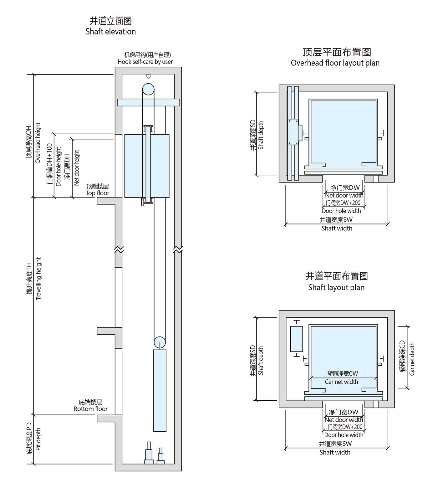
In a machine-room-less lift, everything that would have hung in a machine room is fixed to the top of the shaft: the machine, the diverting sheave and the governor. The building’s job is to provide a beam at the position on the drawing, cast-in anchors of the stated size, and a lifting hook above it. Where the frame sits is settled by the MRL elevator layout before the beam is cast.
The hook is not decoration. It is how the machine gets from the truck to the top of the shaft, and it is also how the machine comes down in twenty years when it is replaced. It is the most frequently missed line on the elevator installation requirements list, because the builder buys it and the lift crew uses it.
Where a machine room exists, three items appear on BST Express Elevator drawings marked for the buyer: the lifting hook, the ventilating window and the exhaust fan. None of them ship with the elevator and all three affect commissioning. A machine room that has been tiled, caged and locked but never ventilated will run hot, and a drive that runs hot derates or trips.
The machine room door on the same BST Express Elevator drawing is dimensioned 1200 by 2100 mm. That is a working dimension rather than a fire rating: it is the size at which a controller and a machine frame can be carried through. Where the door is narrower, the controller arrives in sections and is assembled inside the room, which is slower and dirtier. A door narrower than that is an elevator installation requirements failure that surfaces on delivery day.
Ventilation is not a comfort item either. The ambient range for the machine space is stated on the GA drawing, and a room that runs outside that band shortens the life of the drive and the contactors. Where natural ventilation is not possible, the exhaust fan in the buyer’s scope is the fallback, and it needs its own supply to run. Support above the shaft and ventilation inside the machine room are the two elevator installation requirements most often settled late, and both are settled by somebody who never meets the lift.
Site Access, Storage and Construction Power
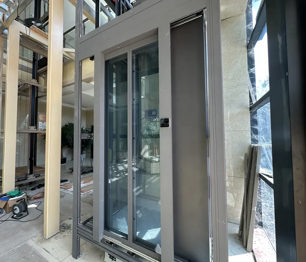
Most installation complaints that reach a factory are not about the lift. They are about a truck that could not reach the door, a crate opened in the rain, or a supply connected to the wrong phase. All three are elevator installation requirements, and all three are cheap to fix before shipping.
Access is decided by the largest single piece. A car frame, a machine and a length of guide rail each have a size, and the route from the road to the shaft has to accept them. That means turning space for the delivery vehicle, a clear path at least as wide as the widest crate, and either a crane, a hoist or rollers for the vertical move. Where a crane is needed it is booked for a day, and a missed booking costs a week. None of this appears on a lift drawing, and yet the crew cannot start without it.
Storage is the second item, and it is the one buyers treat as optional. Components arrive in a crate that has crossed an ocean, and the crate protects them only while it is closed and off the ground. What the shipping and container guide assumes is a dry, lockable room at least the size of the crate footprint, with space to open the lid. Opening crates in a corridor and stacking landing doors against a wall is how sills get bent.
Construction power is the third, and it is the one elevator installation requirements item the site electrician usually controls. The lift needs a three-phase supply at the isolator, sized as the elevator power supply guide sets out, with a correct earth and confirmed phase rotation. A single-phase site supply will run the lights and nothing else. Phase rotation matters more than it sounds: a drive fed with two phases swapped will fault, and the fault reads as a controller problem rather than a site problem.
Who Builds What: The Civil Works Boundary
The most useful page in a contract pack is the one that says which party does which item. Without it, the lifting hook is assumed to be in the crate, the sill support is assumed to be cast, and both assumptions are discovered on the same morning. The table below is the elevator installation requirements list sorted by owner rather than by subject.
| Item | Building contractor | In the crate | Installation team |
|---|---|---|---|
| Hoistway walls, pit slab, overhead slab | Build to the drawing | – | – |
| Pit waterproofing, sump and drainage | Build | – | – |
| Pit ladder, permanent light, socket, stop switch | Supply and fit | – | – |
| Landing openings at door hole size | Cut to DW+200 and DH+100 | – | – |
| Sill support: cast-in angle, flat or recess | Cast or fix | Sill and landing door | Set and align |
| Overhead beam, anchors and lifting hook | Cast and rate the hook | – | Use the hook |
| Machine room slab, door, window, exhaust fan | Build and fit | – | – |
| Three-phase supply to the isolator | Bring in and terminate | Controller and panel | Connect and test |
| Rails, brackets, machine, ropes, doors, controller | – | Supply, packed by floor | Erect and align |
| Buffer plinths and bracket fixing | Cast the plinths | Buffers and brackets | Set and fix |
| Adjustment, load test and handover file | – | Test forms and procedure | Run and record |
Read the middle column as what actually arrives, and the outer columns as what has to exist before it can be used. A buyer who hands this table to their main contractor at the structural stage removes most of the arguments that would otherwise follow. The remaining elevator installation requirements, the ones in the last column, belong to whoever signs the handover.
The Site Survey You Send Before Shipping
The cheapest possible time to find a site problem is before the crate is loaded. A survey sheet filled in by the buyer’s contractor, with measurements and photographs, is what lets a factory confirm a drawing instead of assuming it. It takes an hour on site and it is the difference between a lead time that holds and one that restarts. It is also the one elevator installation requirements document that comes back from the site with numbers in it.
| What to record | How | Why the factory needs it |
|---|---|---|
| Pit depth at four corners | Tape from finished floor level down to the pit slab | Confirms buffer space and the car’s bottom stopping position. |
| Overhead height | Tape from the top finished floor level to the underside of slab or beam | Confirms car top clearance and where the machine hangs. |
| Shaft width and depth at top, middle and bottom | Tape at three heights, on both axes | Reveals taper and twist before rails are cut to length. |
| Plumb deviation at each landing | Plumb wire or laser, offset to the wall face | Predicts whether brackets will need packing. |
| Door hole width and height at every landing | Tape each opening and record it in a table | Confirms the hole size floor by floor, not just at the ground. |
| Machine room slab level and door size | Spirit level and tape | Decides machine placement and how the controller gets in. |
| Supply at the isolator | Photograph the breaker, cable, earth bar and phase labels | Prevents a reversed-phase fault at commissioning. |
| Access route and storage area | Four photographs and a sketch with dimensions | Decides crane or hoist, and the size of delivery vehicle. |
Photographs are worth more than numbers when something is wrong, because they show the whole condition rather than the one dimension somebody chose to measure. Ask for one picture of each opening from inside the shaft, one of the pit floor and one of the isolator. Filled in properly, this sheet turns elevator installation requirements into a record.
Choosing and Briefing the Installation Team
Three models are common: the buyer’s own maintenance team, a local lift contractor, and a crew sent by the factory. The choice changes the site readiness work, because a local contractor brings their own scaffolding and their own definition of ready, while a factory crew arrives with tools and expects conditions to meet a drawing. Whichever model is chosen, the elevator installation requirements themselves do not change.
The brief is the same document set either way: the GA drawing, the civil works boundary table, the survey sheet as built, and the test procedure. Where the team is a local contractor, membership of a trade body such as the National Association of Elevator Contractors is one signal of standing, though it is not a licence and it does not replace checking local certification.
The last item in the brief is who signs the handover. Where the installation team is not the factory’s, the load test and the handover record become the only evidence that the lift was installed as designed. That record is set out in the load test guide, and it should be agreed before work starts rather than argued over at the end.
The Fifteen-Item Site Readiness Checklist
Print this and walk the site with it a month before the crate is due. It condenses the elevator installation requirements above into lines that are either done or are a task with an owner and a date.
- Hoistway walls cast to the drawing, with nothing protruding into the shaft.
- Plumb wire check done at every landing and the offsets written down.
- Pit slab level, waterproofed and draining to a sump or outlet.
- Pit ladder or access door fitted and secure.
- Pit light, socket and stop switch working.
- Buffer plinths cast to position and level.
- Every landing opening measured against the door hole size.
- Sill support cast in or fixed at every landing.
- Overhead beam, anchors and lifting hook in place and rated.
- Machine room slab finished, door hung, ventilating window open.
- Exhaust fan fitted where the drawing calls for one.
- Three-phase supply at the isolator, earthed and phases labelled.
- Access route clear and crane or hoist booked for the delivery day.
- Dry lockable store at least the crate footprint, with room to open the lid.
- Installation team appointed, briefed, and the handover signatory named.
Fifteen items, and the last one is not about the building at all. It is the one that most often turns up unassigned, and it is the reason a finished shaft can sit empty for a month with a crate of equipment beside it. For the freight side of the same project, the freight elevator page covers the load and traffic figures that decide the car before any of this begins. Together the fifteen lines are elevator installation requirements in a form that can be walked with a clipboard.
Frequently Asked Questions
Who is responsible for the shaft, the pit and the landing openings?
The building owner’s contractor. None of those three ship with the elevator, and none of them are part of the installation scope. The GA drawing sets the sizes and the civil works boundary table sets who builds each item, so both belong in the contract before the concrete goes in. These are the three elevator installation requirements most often left unassigned.
Can installation start before the building’s power is connected?
Rails, car and doors can be assembled on temporary power, but the lift cannot be run, adjusted or load tested without the three-phase supply at the isolator. Commissioning is where a missing supply turns into a fortnight of waiting, so the supply is the elevator installation requirements item worth chasing first.
What is the minimum shaft condition a crew will accept?
Plumb to the drawing, dry, clear of obstructions, with access, permanent light and a level pit floor. A crew will work around a great deal, but not standing water, not a dark shaft and not a pit with no way out. Those five are non-negotiable elevator installation requirements.
Do we need a crane to unload an elevator shipment?
It depends on the largest single piece and the route from the truck to the shaft. Where a forklift can reach the shaft door and the machine can be lifted by the overhead hook, no crane is needed. Where the shaft is inside a finished building, a crane or a hoist is booked for the delivery day. Access for that vehicle belongs on the elevator installation requirements list from the start.
How far ahead should the site be ready?
Four to six weeks before the crate lands is a workable target, because concrete work, crane bookings and contractor availability do not move quickly. On a project running late, the checklist above doubles as the list of elevator installation requirements worth paying overtime to finish.
References
- Health and Safety Executive, Safety in the use of lifts (L113) – UK guidance on safe work on lifts and inside lift shafts.
- GB/T 10060-2023, Code for installation acceptance of electric lifts – the Chinese installation acceptance standard, published 7 September 2023 and effective 1 April 2024, replacing the 2011 edition.
- National Association of Elevator Contractors – trade body for lift contractors in North America.
[…] drawing set fixes dimensions, not conditions. The elevator installation requirements cover what the building has to be ready with before a crew can start – the pit, the landing […]
[…] The sequence on site changes with them. The frame has to be set and aligned before the rails go in, because the machine position fixes where the ropes drop. Get that order wrong and the top of the shaft has to be opened up again. The broader sequence for room-based and MRL jobs is set out in elevator installation requirements. […]