


Elevator shaft dimensions are fixed by four inputs, and only one of them is the lift itself: the car size, the drive system, the door type and the load rating. All four are settled weeks before equipment is ordered, while the shaft, pit and headroom are cast together with the structure. This guide sets out the standard elevator shaft dimensions for passenger, hospital, freight, panoramic and home lifts – the same figures our factory in Suzhou, China builds to – so civil works can be sized before the order is committed.
What Fixes Elevator Shaft Dimensions
Four decisions shape every shaft. The car size comes first, because the cabin has to clear the largest thing it will ever carry – a stretcher, a pallet, a sofa or a car. The drive system is second, and it moves the pit and the overhead further than anything else on the list.
A traction lift needs a deep pit and machinery above the shaft; a hydraulic unit needs almost no pit but gives up speed and travel. The door type is third, because a single-slide automatic door, a double-fold door and a manual swing door each need a different landing opening. The load rating is last, and it works indirectly – a heavier rating thickens the platform, the car frame and the guide rails, so the shaft grows even when the cabin stays exactly the same size.
Change any one of the four and the elevator shaft dimensions follow immediately. That is why the vehicle or furniture list, the drive preference and the load rating should all be decided before an architect draws the core.
BST Express Elevator returns a dimensional drawing before the shaft is cast, and it carries shaft width, depth, pit and overhead on one sheet. For a 1,000 kg traction unit the BST figures are 2,400 x 2,200 mm, a 1,500 mm pit and 4,500 mm of overhead.
Elevator Shaft Dimensions at a Glance
The table below is our working reference for a standard single-deck unit with automatic doors, for a one-metre-per-second traction model unless noted. Figures are the net shaft the structure must provide, not the outer concrete face.
| Lift type | Typical capacity | Car W x D (mm) | Net shaft W x D (mm) | Pit depth (mm) | Headroom (mm) |
|---|---|---|---|---|---|
| Passenger | 630-1,600 kg | 1,400-1,950 x 1,350-1,750 | 2,100-2,800 x 2,000-2,600 | 1,500 | 4,500 |
| Hospital | 1,600-2,000 kg | 2,300-2,500 x 1,500-1,650 | 2,900-3,200 x 2,300-2,600 | 1,500-1,600 | 4,500-4,800 |
| Freight | 1,000-5,000 kg | 1,800-3,400 x 2,000-4,000 | 2,600-4,800 x 2,500-4,600 | 1,500-1,600 | 4,500-5,000 |
| Panoramic | 800-1,600 kg | 1,600-1,950 x 1,400-1,750 | 2,300-2,800 x 1,900-2,400 | 1,500 | 4,500 |
| Home or villa | 250-400 kg | 620-820 x 620-820 | 1,000-1,300 x 900-1,200 | 150-450 | 2,700-3,200 |
| Car lift | 3,000-5,000 kg | 2,300-3,400 x 5,000-7,000 | 4,000-4,800 x 5,900-7,560 | 1,500-1,600 | 4,800-5,000 |
Two cautions before these figures are used. The ranges are genuine, because manufacturers position guide rails, counterweights and door mechanisms differently – two cars can be identical while the shafts are not. And every number assumes the machine sits above the shaft: a machine-room-less design removes the room, not the overhead. Always check the final elevator shaft dimensions against a drawing stamped with your project reference.
BST Express Elevator quotes the same four figures on every project sheet, because a shaft built from a brochure number is the costliest error in this category. A 630 kg unit at 2,100 x 2,000 mm and a 1,600 kg unit at 2,800 x 2,600 mm are BST working sizes from live orders.
Shaft Width and Depth: How They Follow the Car
Two rules cover the first pass at any shaft. Width equals the widest car dimension plus 400-500 mm for rail and door clearance, and depth equals the deepest car dimension plus 250-600 mm. The exact allowance depends on where the counterweight sits. The car measurements those allowances wrap around are set out in our elevator car dimensions guide.
| Counterweight position | Effect on shaft width | Effect on shaft depth | When we recommend it |
|---|---|---|---|
| Side (alongside the car) | Car width + 700-1,200 mm | Car depth + 250-400 mm | Wide sites; the common default |
| Rear (behind the car) | Car width + 400-600 mm | Car depth + 600-900 mm | Narrow frontages and shallow shafts |
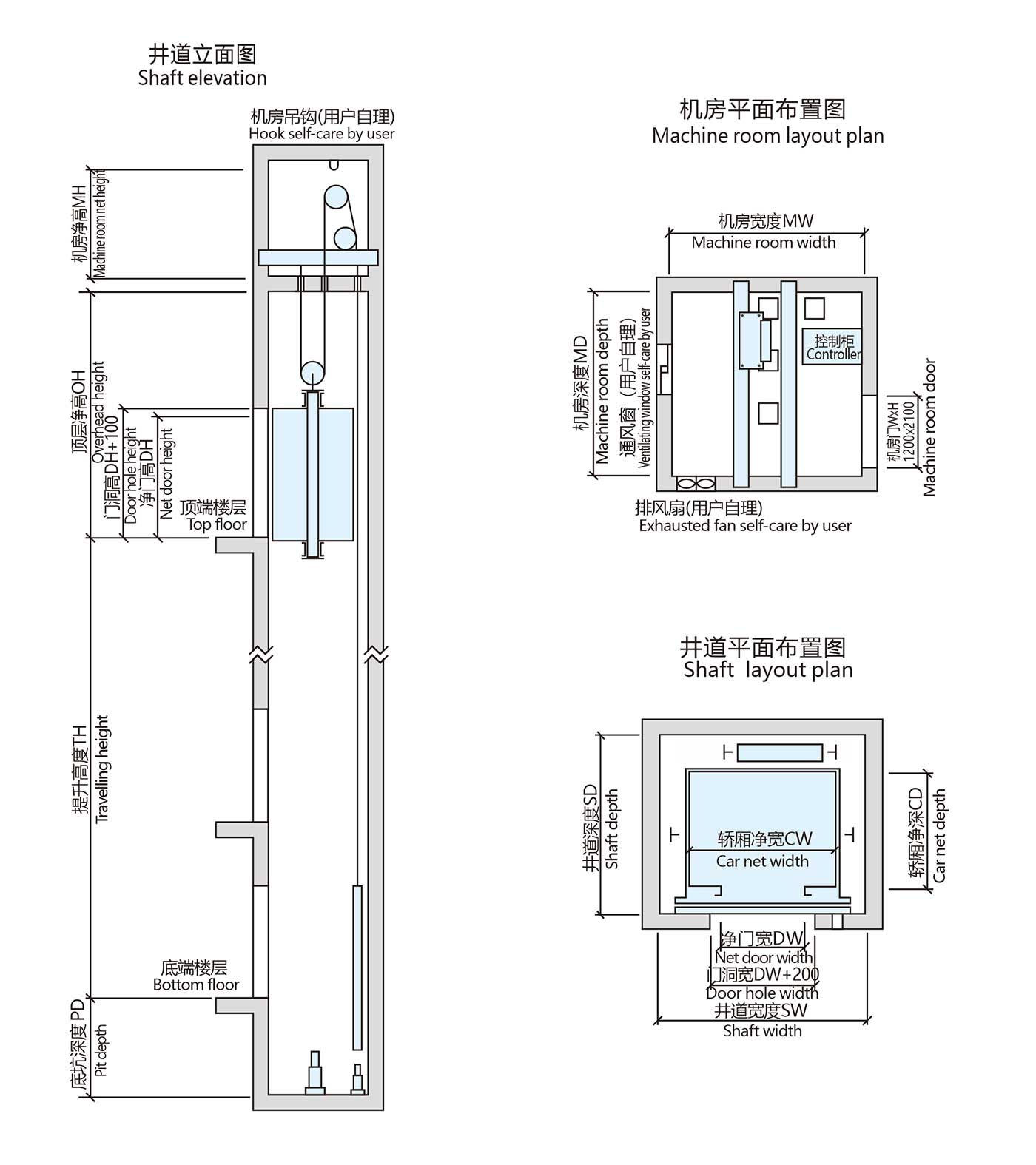
One definition matters before any of these figures is used. Net shaft dimensions are the clear opening the structure has to provide, measured between finished wall faces – not the outer concrete line. Architects draw outside faces and suppliers quote inside ones, and the gap between the two is where most pre-pour errors come from. Ask for elevator shaft dimensions on the inside face, and mark the wall thickness separately.
The rear-counterweight layout is the one that saves frontage, which is why it dominates villa and retrofit projects. On a shallow shaft, a counterweight at the rear can also be moved to steel blocks, and that single change often makes an otherwise impossible elevator shaft dimensions package work.
Pit Depth and Headroom: The Two Numbers Cast in Concrete
Pit depth is measured from the finished lower floor to the bottom of the shaft. Headroom, or overhead, is the clear height from the top landing to the underside of the shaft ceiling. Both are structural, and both are far cheaper to build correctly the first time than to correct afterwards, once the elevator shaft dimensions have been agreed on a stamped drawing.
| Drive system | Pit depth (mm) | Headroom (mm) | Best fit |
|---|---|---|---|
| Traction, machine above | 1,500 | 4,500 | Multi-storey buildings, 0.5-1.75 m/s |
| Traction, machine-room-less | 1,500 | 4,200-4,500 | Buildings with no plant floor to spare |
| Hydraulic | 200-300 | 3,200-3,600 | Two to four stops, retrofits, low ceilings |
| Strong drive, machine on top | 150-300 | 3,200 | Villa and compact shafts |
| Strong drive, machine at the rear | 150-300 | 2,800 | Where headroom is the binding constraint |
That gap explains the most common question buyers ask. Under a three-metre ceiling no standard traction lift fits at all, because the overhead alone runs to 4,200 mm. What fits is a hydraulic or strong-drive unit with short travel, or a raised floor and a full-height shaft. Decide the drive system before the floor-to-floor height is locked, not after.
Two practical notes on the pit. Allow for drainage and a sump, because a pit that floods is an expensive repair. And measure to the finished floor level on both ends: a 60 mm screed left out of the calculation is enough to change the elevator shaft dimensions that were agreed on the drawing.
BST Express Elevator builds hydraulic and strong-drive units for the low-ceiling case, where the pit runs from 150 to 300 mm instead of the 1,500 mm a traction machine needs. BST ships those models as a machine-room-less package.
Elevator Shaft Dimensions by Lift Type
Passenger lifts are the most regular family. A 630 kg unit for eight people works in a shaft of roughly 2,100 x 2,000 mm; a 1,000 kg unit for thirteen people needs about 2,400 x 2,200 mm; a 1,600 kg unit goes to about 2,800 x 2,600 mm. Machine-room-less models save the plant floor, not the shaft. Passenger elevator shaft dimensions vary little between makers, which makes this family the safest to budget from a table. Our passenger elevator range lists the capacities we build.
BST Express Elevator builds the 630, 1,000 and 1,600 kg passenger units on one platform, so the three shafts above come from a single drawing family. A BST order returns all four figures on one revision-controlled sheet.
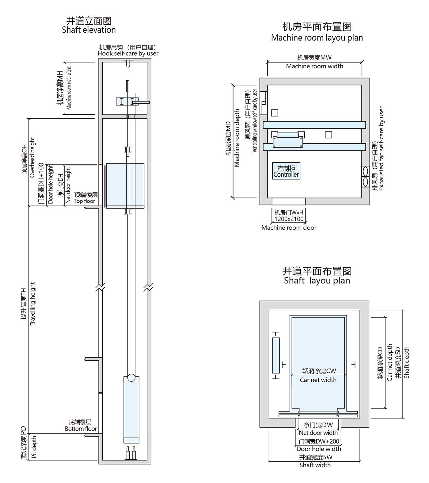
Hospital lifts are sized by the stretcher, not by the passenger count. A 1,600 kg bed lift normally carries a car of about 2,400 x 1,500 mm, which keeps a 2,200 mm stretcher flat and lets staff work at both ends. That depth requirement is why medical elevator shaft dimensions rarely shrink below 2,900 mm of shaft width. Our hospital elevator range covers these sizes in standard and machine-room-less builds. The shaft-side figures a hospital project has to supply with the RFQ are listed in what a hospital lift supplier needs from the shaft.
Freight and goods lifts are driven by the load class and the pallet or trolley that has to fit. A 2,000 kg unit typically needs a car of about 2,000 x 2,700 mm inside a shaft of 2,800 x 3,100 mm. Because a rating alone says little, we size freight elevator shaft dimensions from the platform area and the door configuration rather than from the tonnage, and the choice between the two types is set out in the comparison of a passenger elevator and a freight elevator. Our freight elevator page lists the load classes we build.
Panoramic lifts use a glass car inside a steel or concrete shaft, and the plan usually matches a passenger unit of the same capacity. The difference is the glazing: the car needs a 100-150 mm gap on the viewing side, so a panoramic shaft is rarely smaller than its standard equivalent.
Where the shaft is exposed to weather or to a public facade, confirm the glazing detail at the same time as the elevator shaft dimensions, because both are drawn on the same section. The glass specification behind a panoramic cabin is the other half of that drawing, and it is cheaper to fix before the shaft is cast than after the glass has been cut.
Home and villa lifts run at the other end of the scale. Our compact hand-door series uses car widths and depths of 620, 670, 720, 770 and 820 mm with a 2,100 mm car height, standard pit of 200 mm and 150 mm as the minimum, and headroom from 2,700 mm on a rear-counterweight traction model up to 3,200 mm for a machine-on-top strong drive. The full range of residential elevator shaft dimensions is in our home elevator shaft dimensions guide.
BST Express Elevator sets the villa pit at 200 mm as standard and 150 mm as the minimum, with headroom between 2,700 mm and 3,200 mm depending on the drive. Those four figures decide whether a BST home lift fits an existing house.
Car lifts are the largest and least forgiving. A 3,000 kg unit needs a car of about 2,300-2,600 x 5,000-5,700 mm inside a shaft of 4,000-4,250 x 5,900-6,200 mm, with a pit of 1,500-1,600 mm and roughly 4,800 mm of overhead. Those figures are set out in detail in our car elevator dimensions guide.
Standard Elevator Shaft Sizes: The Reference Table
Standard elevator shaft sizes track the rated load in a near-straight line: 630 kg in a 2,100 x 2,000 mm net shaft, 1,000 kg in 2,400 x 2,200 mm, and 1,600 kg in 2,800 x 2,600 mm. BST Express Elevator quotes those three figures on most passenger enquiries.
The reference table below sets out those elevator shaft dimensions across the standard capacity steps, with the clear landing door opening that pairs with each load.
| Rated load | Persons (75 kg) | Net shaft W x D (mm) | Clear door opening (mm) | Typical building |
|---|---|---|---|---|
| 630 kg | 8 | 2,100 x 2,000 | 800 | Apartment blocks, small offices |
| 800 kg | 10 | 2,250 x 2,050 | 900 | Mid-rise residential, hotels |
| 1,000 kg | 13 | 2,400 x 2,200 | 900 | Offices, retail, hotels |
| 1,250 kg | 16 | 2,550 x 2,350 | 1,000 | Commercial buildings, clinics |
| 1,600 kg | 21 | 2,800 x 2,600 | 1,100 | Hospitals, high-traffic towers |
The 800 kg and 1,250 kg rows are the industry’s adjacent standard steps rather than separate platforms. BST Express Elevator builds the 630, 1,000 and 1,600 kg passenger units on one drawing family, so a project that starts from the table above still ends with a single revision-controlled shaft sheet. Buyers who search for standard lift shaft sizes land on the same numbers, because lift and elevator describe one and the same shaft.
Read the table for shaft width and depth only. Pit depth and headroom are set by the drive system and the rated speed, not by the load, so a 1,000 kg lift at 1.0 m/s and the same lift at 1.75 m/s share shaft dimensions but not a pit.
Two habits keep a project on schedule: check the shaft against the table before the concrete is poured, and treat every figure in it as a planning value until the approved general arrangement drawing confirms it. BST Express Elevator returns that drawing with the quotation, so the number on the drawing and the number in the table can be compared before anyone orders concrete.
Lift Shaft Dimensions: The UK and Commonwealth Terms
Buyers in the United Kingdom, Ireland, Australia, India, South Africa and Singapore write lift where North American buyers write elevator, and the same split runs through the drawings: lift well for the shaft, pit for the pit and headroom or overhead for the top clearance. The numbers themselves do not move.
What does move is the standard quoted alongside them. British and Commonwealth projects normally reference the EN 81 series through their national adoption, United States projects reference ASME A17.1, and both converge on the ISO 8100 series for lift design. When you send a drawing, state the code you are working to – it prevents the kind of misunderstanding that turns into a rebuilt elevator shaft dimensions package.
For the components inside those shafts, our introduction to what an elevator is covers the parts and drive systems first.
Machine Room or Machine-Room-Less: What Changes in the Building
Where the machine sits changes the building rather than the cabin, and it still moves the elevator shaft dimensions you have to build. A machine room above the shaft adds a floor of plant space and remains the simplest layout to service. A machine-room-less unit houses the drive inside the shaft and raises the overhead requirement instead, which is why an MRL elevator is judged on overhead rather than on shaft width.
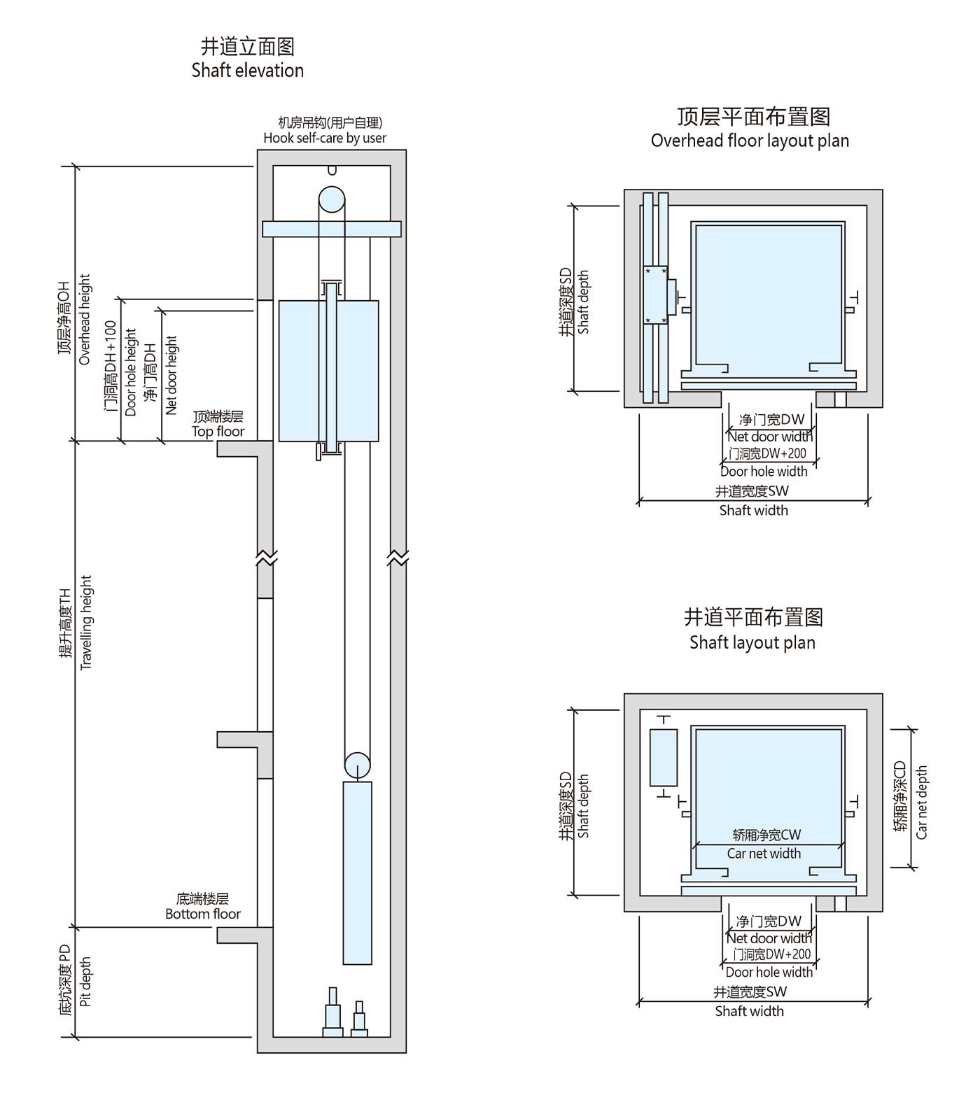
Putting the machine at the base is common on hydraulic units: it frees the roof but consumes floor area beside the shaft. None of the three touches the platform or the car, so the decision belongs with the architect as much as with the supplier – and it is worth making before the shaft walls are poured, because it moves the plant space and the elevator shaft dimensions at the same time.
Steel Structure Shafts: When the Dimensions Change
A steel structure shaft is the practical answer when there is no concrete shaft and no reasonable way to build one – an existing building, a stairwell, a courtyard or a factory mezzanine. The internal net dimensions stay the same, because the car and the rails do not move. What changes is the wall thickness: a steel frame is typically thinner than a reinforced concrete wall, so the outer footprint can be smaller even though the clear elevator shaft dimensions are identical.
Three points decide whether a steel shaft works. The frame must be designed for the guide rail loads, not just for the weight of the car. Fire rating has to be agreed with the local authority, because a steel structure often needs additional protection. And the installation tolerance is tighter than on a concrete shaft, so the foundation and the base plates are worth checking twice before the frame is bolted down.
Where the structure is steel, we supply the complete package – frame, car, doors and drive – so the clear elevator shaft dimensions come from one drawing rather than two suppliers. Where only stairwell space is available, a panoramic car in a steel shaft is usually the answer, and it is often the only layout that fits at all.
BST Express Elevator supplies the steel frame, car, doors and drive as one package, so the clear shaft dimensions come from a single drawing. A 3,000 kg car lift package from BST runs to 4,000 x 5,900 mm inside the frame.
Pre-Pour Checklist: Ten Items to Confirm Before the Concrete
Bring this list to the first technical meeting and the conversation moves from price to engineering within ten minutes. It also prevents the most expensive mistake in this category: building a shaft that suits the lift you were quoted, then finding the drawings were never reconciled with the loads you actually carry.
- Net shaft width and depth at every floor, not only at the entrance level
- Pit depth with drainage, sump and waterproofing already detailed
- Headroom above the top landing, measured to the finished soffit
- Landing door opening width and height, plus the clear approach in front of it
- Structural loads and rail bracket fixing points on the shaft wall
- Machine room size, ventilation and access, unless the unit is machine-room-less
- Power supply: a three-phase feed sized to the motor, plus lighting and a service socket
- Installation access, because the largest single package still has to reach the shaft
- Storey heights, so every landing finishes level with the floor slab
- The code you are working to – ASME A17.1, the EN 81 series or the local equivalent
One last habit saves more money than any of the ten. Send the supplier the vehicle list or the furniture list, the floor-to-floor heights, the port of discharge and a sketch of the space available, and ask for a dimensional drawing before a price. A quotation without elevator shaft dimensions on it is just a number, and comparing two of them tells you nothing.
BST Express Elevator runs the same pre-pour checklist on every project and returns it with the drawing, so all 10 of them are confirmed before the concrete is placed. A BST project that skips it pays for the shaft twice.
The pour only settles the sizes. What the shaft has to be ready with afterwards – a dry pit, openings at the door hole size, overhead support and a three-phase supply – is a second list, and it is the one that stops a crew: elevator installation requirements, checked before the crate ships.
Frequently Asked Questions
What are standard elevator shaft dimensions? For a 1,000 kg passenger lift with a traction drive, plan on a car of about 1,600 x 1,500 mm inside a net shaft of about 2,400 x 2,200 mm, with a 1,500 mm pit and roughly 4,500 mm of headroom. Freight, hospital and car lifts each add to those figures, which is why we confirm elevator shaft dimensions against your own drawing before quoting.
What is the minimum pit depth? A conventional traction lift needs about 1,500 mm. A hydraulic or strong-drive unit can work from a 150-300 mm pit, which is why those drives dominate retrofits and buildings with low ceilings.
How much headroom does an elevator need? Around 4,500 mm above the top landing for a standard traction unit with the machine above the shaft. A machine-room-less model still needs roughly 4,200 mm, because the drive moves inside the shaft rather than out of the building.
Do lift shaft dimensions differ from elevator shaft dimensions? No. Lift and elevator describe the same equipment, and the dimensions are identical. The difference is terminology: British and Commonwealth projects say lift well, pit and headroom, while North American projects say hoistway, pit and overhead.
Can a shaft be made smaller after the concrete is poured? Rarely without cost. The practical alternatives are a different drive system, a reduced car size or a steel structure shaft built inside the existing space. That is why the drive, the car and the load rating should all be fixed before the structure is cast.
These figures follow the design benchmarks published by the standards bodies: ASME A17.1 safety code for elevators and escalators in the United States, EN 81-20 and EN 81-50 through CEN-CENELEC in Europe, and the ISO 8100 series for lift design. Verification points for importers are set out in our elevator CE certification guide, and the full ordering sequence in how to buy elevators from China.
Send us your shaft width, depth, pit depth, headroom and floor-to-floor heights, and we return a dimensional drawing with a factory-direct quotation for the unit that fits – not a brochure figure. We build passenger, hospital, freight, panoramic, home and car lifts as a CE-certified elevator manufacturer in China, and every unit runs under full load on the test bench in Suzhou before packing. Ready to size the shaft? Send your drawings to our export team.
[…] above the top landing. Pit depth and headroom allowances for other lift types are compared in our standard elevator shaft dimensions guide. It lifts at 0.25–0.5 m/s, and a 3,000–5,000 kg machine draws around 15–18.5 […]
[…] only a starting point. The full relationship, including pit depth and headroom, is set out in our elevator shaft dimensions guide, which is the companion piece to this page: that one covers the civil envelope, this one […]
[…] than the car itself, the geometry a China hospital elevator supplier works to is set out in the elevator shaft dimensions guide, and the trade-off between car size and capacity is covered in elevator car dimensions and […]
[…] walk manufacturer in China. Projects that also need vertical transport can compare the figures with elevator shaft dimensions so the shaft and the concourse are planned against the same set of […]
[…] are approved rather than after a buyer imports elevators to Eastern Europe on a nominal figure. The elevator shaft dimensions and elevator car dimensions guides set out the standard sizes and how the car is fixed against the […]
[…] are a different problem. Pit depth, overhead height and shaft width are set out in the elevator shaft dimensions guide, together with the pre-pour checks that fix those numbers before concrete. Read that first if the […]
[…] wrong voltage at the drive, which presents as nuisance tripping rather than as a wiring fault. The elevator shaft dimensions guide covers where the riser and the junction box sit relative to the […]
[…] the leaf size are three different numbers, and the shaft drawing usually fixes only the first. The elevator shaft dimensions guide sets out how the opening relates to the well, and the elevator quotation checklist shows […]